05 - Networking
- Networking Fundamentals
- Virtual Private Cloud (VPC)
- * Multifactor authentication, ID federation and/or IP blocks.
- Global DNS (Route 53)
Networking Fundamentals
OSI Model
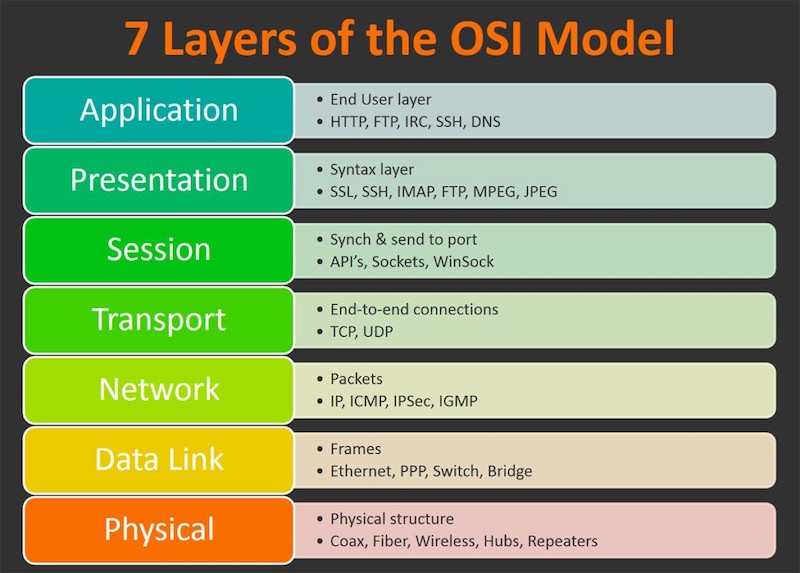
The Open Syste Interconnection (OSI) Model is a standard used by networking manufacturers globally. It was created and published in 1984; it splits all network communications into seven layers. Each layer servers the layer that’s above it plus the layer beneath it which adds additional capabilities. Data between two devices travels down the stack on the device’s A-side (wrapped at each layer) and gets transmitted before moving up the stack at the device B-side (where the wrapping gets stripped aways at every stage). The data wrapping process is called encapsulation.
-
At Layer 1 (Physical), networks use a shared medium where devices can transmit signals and listen. Layer 1 showcases how data gets received and transmitted while taking into consideration the medium, voltages, and RF details.
-
Layer 2 (Data Link) adds MAC addresses that can be used for named communication between two devices on a local network. Aditionally, layer 2 adds control over the media, avoiding cross-talk, this allows a back-off time and retransmission. L2 communications use L1 to broadcast and listen. L2 runs on top of L1.
-
The Network Layer (L3) allows for unique device-to-device communcation over interconnected networks. L3 devices can pass packets over tens or even hundreds of L2 networks. The packets remain largely unchanged during this journey - travelling within different L2 frames as they pass over various networks.
-
L4 (Transport) adds TCP and UDP. TCP is designated for reliable transport, and UDP is aimed at speed. TCP uses segments to ensure data is received in the consistent order and adds error checking and “ports” allowing different stream of communications to the same host.
-
L5 (Session) adds the concept of sessions, so that request and reply communication streams are viewed as a single “session” of communication between client and server.
-
L6 (Presentation) adds data converstion, encryption, compression,and standard that L7 can use. L7(Application) is where protocols (such as HTTP, SSH, and FTP) are added.
IP Addressing
IPv4 addresses are how two devices can communicate at layer 4 and above of the OSI seven-layer model. IP address (IPs) are actually 32-bit binary values but are represented in dotted-decimal notation to make them easier for humans to read and understand.
IPs are split into a network part and host part. The netmask (eg. 255.255.255.0) or prefix (e.g. /24) shows where this split occurs.
| IP | 10 | 0 | 0 | 0 |
|---|---|---|---|---|
| Binary | 10000000 | 00000000 | 00000000 | 00000000 |
| Subnet Mask | 255 | 255 | 255 | 0 |
| Prefix /24 | 11111111 | 11111111 | 11111111 | X |
Subnetting
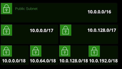
Subnetting is a process of breaking a network down into smaller subnetworks. You might be allocated a public range for your business or decide on a private range for a VPC. Subnetting allows you to break it into smaller allocations for use in smaller network.
If you pick 10.0.0.0/16 for your VPC, it’s a single network from 10.0.0.0 to 10.0.255.255 and offers 65,536 addresses. With a certain size of VPC, increasing the prefix creates two smaller networks. Increasing agian creates four even smaller networks. Increasing again creates eight smaller and so on.
Firewall
A firewall is a device that historically sits at the border between different networks and monitors traffic flow between them. A firewall is capable of reading packet data and either allowing or denying traffic based on that data.
Firewall establish a barrier between networks of different security levels and historically have been the first line of defense against perimeter attacks.
Proxy Servers
A proxy server acts as a gateway between you and the internet. It’s an intermediary server separating end users from the websites they browse. Proxy servers provide varying levels of functionality, security, and privacy depending on your use case, needs, or company policy.
A proxy server is a type of gateway that sits between a private and public network. Proxy servers can also choose to pass on traffic or not based on network layer appliances eg, username or element of corporate identity. It inspects outbound requests from an on-premise or private network client
Virtual Private Cloud (VPC)
Virtual Private Cloud (VPC):
- A private network within AWS. It’s your private data center inside the AWS platform.
- Can be configured to be public/private or a mixture
- Regional (can’t span regions), highly available, and can be connected to your data center and corporate networks
- Isolated from other VPCs by default
- VPC and subnet: Max /16 (65,536 IPs) and minimum /28 (16 IPs)
- VPC subnet cannot span AZs (1:1 Mapping)
- Certain IPs are reserved in subnets
Regional Default VPC:
- Required for some services, used as a default for most
- Pre-configured with all required network/security
- Configured using /16 CIDR Block (172.31.0.0/16)
- A /20 Public subnet in each AZ, allocating a public P by default
- Attached internet gateway with a “main” route table sending all IPv4 traffic to the internet gateway using a 0.0.0.0/0 route
- A default DHCP option set attached
- SG: Default - all from itself, all outbound
- NACL: Default - allow all inbound and outbound
Custom VPC:
- Can be designed and configured in any valid way
- You need to allocate IP ranges, create subnets, and provision gateways and networking, as well as design and implement security
- When you need multiple tiers of a more complex set of networking
- Best practise is to not use default for most production things
VPC Routing
- Every VPC has a virtual routing device called the VPC Router.
- It has an interface in any VPC subnet known as the “subnet+1” address for 10.0.1.0/24, this would be 10.0.1.1 / 32
- The router is highly available, scalable, and controls data entring and leaving the VPC and its subnets.
- Each VPC has a “main” route table, which is allocated to all subnets in the VPC by default. A subnet must have one route table.
- Addditional “custom” route tables can be created and associated with subnets - but only one route table (RT) per subnet.
- A route table controls what the VPC router does with traffic leaving a subnet.
- An internet gateway is created and attached to a VPC (1:1). It can route traffic for public IPs to and from internet.
Routes
- A Route Table is a collection of routes that are used when traffic from a subnet arrives at the VPC router.
- Every route table has a local route, which matches the CIDR of the VPC and lets traffic be routed between subnets.
- A route contains a destination and a target. Traffic is forwarded to the target if its destination matches the route destination.
- If multiple routes apply, the most specific is chosen. A/32 is choen before a /24, before a /16.
- Default routes (0.0.0.0/0 v4 and ::/0 v6) can be added that match any traffic not already matched.
- Targets can be IPs or AWS networking gateway objects.
- A subnet is a public subnet if it is (1) configured to allocate public IPs, (2) if the VPC has an associated internet gateway, and (3) if that subnet has a default route to that internet gateway.
An Internet gateway can be attached to only a single VPC; A VPC can have a single Internet Gateway. Internet Gateway is Highly Available by Design.
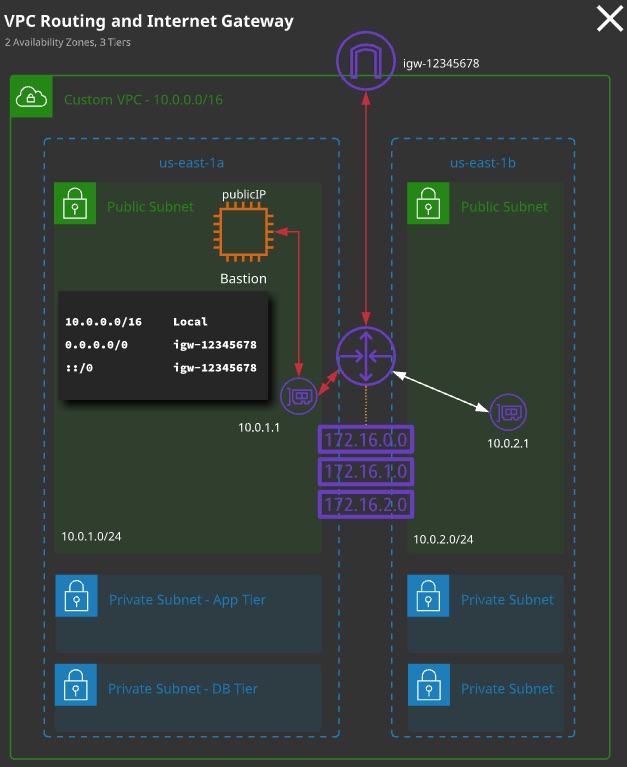
Bastion Hosts (Jump Boxes)
- A host that sits at the perimeter of a VPC
- It functions as an entry point to the VPC for trusted admins.
- Allows for update or configuration tweaks remotely while allowing the VPC to stay private and protected.
- Generally connected to via a SSH (Linux) or RDP (Windows)
- Bastion hosts must be kept updated, and security hardened and audited regularly.
- Multifactor authentication, ID federation and/or IP blocks.
NAT Gateway
NAT (Network Address Translation) is a process where the source or destination attribute of an IP packets are changed. Static NAT is process of 1:1 translation where an internet gateway converts a private address to public IP Address. Dynamic NAT is a variation that allows many private IP to get outgoing internet access using smaller number of public IP (generally one). Dynamic NAT is provided within AWS using NAT gateway that allows private subnet in AWS VPC to acess the internet.
NAT Gateway is used to enable instances ina private subnet to connect to the internet or other AWS services, but prevent the internet from initiating a connection with those instances.
NAT Gateway are not HA by Design. It is inside single Available Zone. It scales well with load.
Network ACLs
- Network ACLs operate at Layer 4 of the OSI Model (TCP/UDP and below)
- A subnet has to be associated with a NACL - either the VPC default or a custom NACL
- NACLs only impact traffic crossing the boundary of a subnet. (If communication occurs within a subnet, no NACLs are involved)
- NACLs are collection of rules that explicitly allow or deny traffic based on its protocol, port range, and source/destination.
- Rules are processed in number order, lowest first. When a match is found, that action is taken and processing stops.
- NACLs have two set of rules: inbound and outbound.
With NACL, you cannot reference logical AWS resources because it operates at Layer 4 or below of OSI Model. But with NACL, you can explicitly deny routes.
VPC Peering
- Allows direct communication between VPCs
- Services can communicate using private IPs from VPC to VPC
- VPC peers can span AWS accounts and even regions (with some limitations)
- Data is encrypted and transits via the AWS global backbone.
- VPC peers are used to link two VPCs at layer 3: company mergers, shared services, company and vendor, auditing.
Important Limits and Considerations:
- VPC CIDR blocks cannot overlap
- VPC peers connect two VPCs - routing is not transitive
- Routes are required at both sites (remote CIDR -> peer connection)
- NACLs and SGs can be used to control access
- SGs can be referenced but not cross-region
- IPv6 support is not available cross-region
- DNS reoslution to private IPs can be enabled, but it’s a setting needed at both sides.
Steps to Enable VPC Peering
- Create VPC Peering Object
- Add Route FROM VPC Subnet and TO VPC Peering Object.
- Update Security Group to Unblock the Inbound and Outbound Rules
- Ensure there aren’t any connection Blocking Rules in Network ACLs
VPC Pairing doesn’t support Transitive Routing
VPC Endpoints
VPC Endpoints are gateway objects created within a VPC. They can be used to connect to AWS public servers without the need for the VPC to have an attached internet gateway and be public.
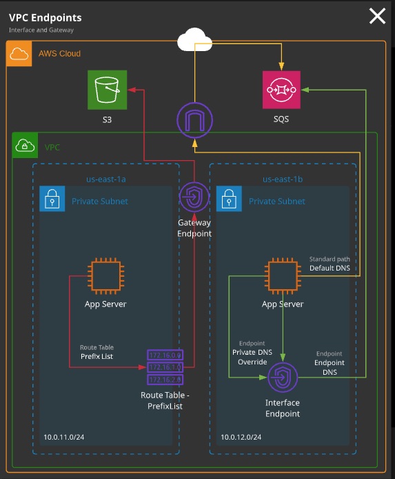
VPC Endpoint Types:
- Gateway endpoints: Can be used for DynamoDB and S3
- Interface endpoints: Can be used for everything else (e.g. SNS, SQS)
When to Use a VPC Endpoint:
- If the entire VPC is private with no IGW
- If a specific instance has no public IP/NATGW and needs to access public services
- To access resources restricted to specific VPCs or endpoints (private S3 bucket)
Limitations and Considerations:
- Gateway endpoints are used via route table entries - they are gateway devices. Prefix lists for a service are used in the destintation field with the gateway as the target.
- Gateway endpoints can be restricted via policies
- Gateway endpoints are HA across AZs in a region
- Interface endpoints are interfaces in a specific subnet. For HA, you need to add multiple interfaces - one per AZ
- Interface endpoints are controlled via SGs on that interface. NACLs also impact traffic.
- Interface endpoints add or replace the DNS for the service - no route table updates are required.
- Code changes to use the endpoint DNS, or enable private DNS to override the default service DNS.
Egress-only internet gateways provide IPv6 instances with outgoing access to the public internet using IPv6 but prevent the instances from being accessed from the internet.
NAT isn’t required with IPv6, and so NATGW’s are compatible with IPv6. Egress-only gateways provide the outgoing-only access of a NATGW but do so without adjusting any IP addresses.
Global DNS (Route 53)
Hosted Zone
A zone or hosted zone is a container for DNS records relating to a particular domain (e.g, google.com). Route 53 supports public hosted zones, which influce the domain that is viable from the internet and VPCs. Private hosted zones are similar but accessible only from the VPCs they are associated with.
Public Zones
- A public hosted zone is created when you register a domain with Route 53, when you transfer a domain into Route 53, or if you create one manually.
- A hosted zone will have “name servers” - these are the IP addressess you can give to a domain operator, so Route 53 becomes “authoritative” for a domain
Private Zones
- Private Zone are created manually and associated with one or more VPCs
- Private zones need
enableDnsHostnamesandenableDnsSupportenabled on VPC
Routing Policy
Simple Routing
A simple routing policy is a single record within a hosted zone that contains one or more values. When queried a simple routing policy record returns all the values in a randomized order.
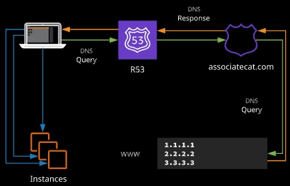
Pros: Simple, the default, even spread of requests
Cons: No performance control, no granual health checks, for alias type
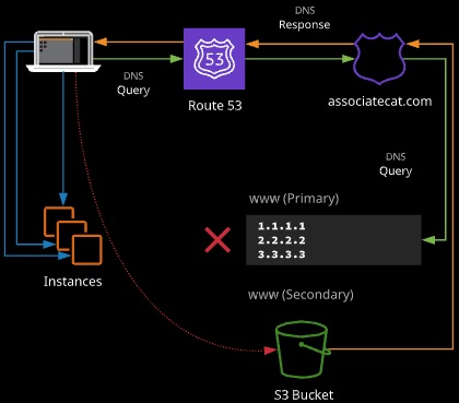
Failover Routing
Failover routing allows you to create two records with same name. One is designed as the primary and another as secondary. Queries will resolve to the primary - unless it is unhealthy, in which the Route 53 will respond with the secondary.
(Single Primary Record Type and Single Secondary Record Type)
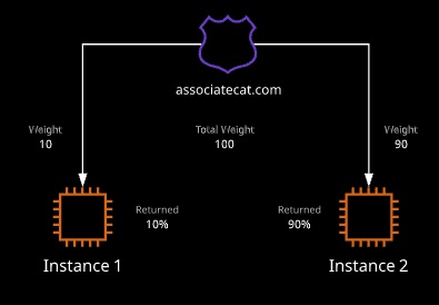
Weighted Routing Policy
Weighted routing can be used to control the amount of traffic that reaches specific resources. It can be useful when testing new software or when resources are being added or removed from.
Latency Based Routing
Checks with Latency Database with latency based host in DNS
GeoLocation based Routing
Geolocation routing lets you choose the resource that server your traffic based on the geographic region from which queries originate.